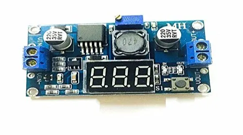
The DC-DC Step-down Adjustable Power Supply Module with 3digit LED Display is based on monolithic integrated circuit LM2596, ideally suited for easy and convenient design of a step−down switching regulator (buck converter). It is capable of driving a 2.0A load with excellent line and load regulation. This device is available in adjustable output version and it is internally compensated to minimize the number of external components to simplify the power supply design. Easy to connecting of power wires. PowerIn to the green terminal block, PowerOut to blue. This module has 3 digit voltmeter display on board. With the button, you can change the display voltmeter information to input or to output.
Specification:
- Input Voltage Range: 4V-40V DC
- Output Voltage Range: 1.25V-37V DC adjustable
- Output Current: 2A
- Voltmeter Range:0 to 40V,error +-0.1V
- The Voltmeter Resolution: ±0.1V
- The Voltmeter Digital Display Range: 0v-45v
- The Voltmeter Input Voltage Range: Dc 4v-40v
- Output Voltage: Continuous Adjustable (1.3v-37 V)
- Output Current: 2a
Features:
- Output 3A, suggest power over 15w pls install the heat sink
- The input and output voltage can display or be closed.
- With reverse connection and overheat protection and short circuit protection,
- Often use for DIY adjustable regulated power supply and other Fixed voltage out 12V turn to 3.3V, 12V to 5V, 24V to 5V, 24V to 12V, 36V to 24V
Output Voltage Calibration Steps:
- Step 1: Adjust the right button so that the “OUT” LED is lighted, the voltmeter shows the value of output voltage; Press the right button for more than 2 seconds, release the voltmeter and “OUT” LED flashes in synchronization so that you enter the output voltage calibration mode.
- Step 2: Press the right button (normal speed), the voltage value is adding up a unit; Press the left button, minus a unit; Due to a unit being less than 0.1V, the minimum voltage display to 0.1V, so you need to continuously press 1-5 times to see the voltmeter change 0.1V, how many times voltmeter change 0.1V by pressing the key, depending on the current display voltage, the higher the voltage, the fewer the number of press.
- Step 3: Press the right button for more than 2 seconds, release, to exit the output voltage calibration mode. All parameters are set to automatically power down to save. Input voltage calibration steps
- Step 1: Adjust the right button so that the “IN” LED is lighted, the voltmeter shows the value of input voltage; press the right button for more than 2 seconds, release, voltmeter and “IN” LED flashes in synchronization so that you enter the input voltage calibration mode.
- Steps 2 and 3: Consistent with the output voltage calibration method.

